What the cooling floor is and why it decides ice quality
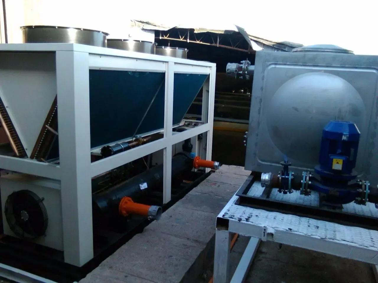
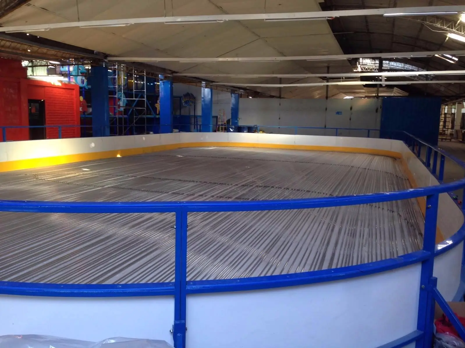
An ice rink has three parts: the cooling floor, the machinery that produces the cold (chiller and pumps) and the barriers. The chiller cools the coolant, the pump circulates it through a network of pipes several kilometres long beneath the surface, and the water flooded on top freezes.
The less energy lost along the way, the better the ice and the lower the consumption. We design the whole system at once, from the hydraulic calculation to the insulation, to keep that loss to a minimum. The design is a registered industrial design in Spain and the European Union, and patented in Mercosur.
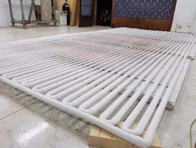
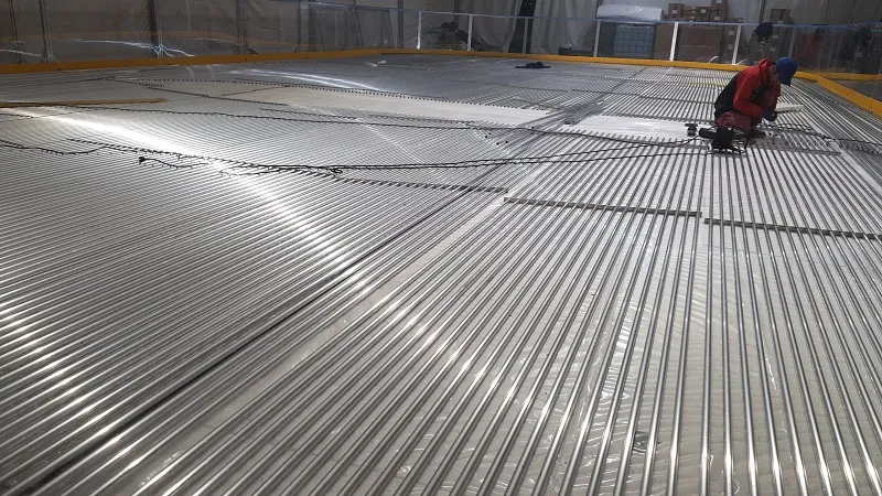
2 mm tempered aluminium pipework
All the cooling floor pipework is 2 mm wall tempered aluminium. Aluminium transfers cold very well to the water above it and does not degrade with temperature changes, so it lasts many years without maintenance.
Many rinks on the market use rubber mats (EPDM) or polyethylene pipe. Their advantage is speed: they are simply rolled out. The trade-off is that rubber fatigues with use and commonly gets punctured during installation, sometimes while the rink is open, and polyethylene shrinks in the cold and can become brittle below -10 °C. With aluminium pipework there are no punctures and no coolant leaks.
Aluminium versus rubber: the material data
The difference lies in the physical properties of each material. These are the values from the MakeItFrom materials database:
| Property | Aluminium | EPDM rubber | Difference |
|---|---|---|---|
| Thermal conductivity | 200 W/m·K | 0.2 W/m·K | about 1,000 times higher |
| Thermal diffusivity | 82 mm²/s | 0.1 mm²/s | about 820 times higher |
| Tensile strength | 100 to 210 MPa | 13 MPa | 8 to 16 times higher |
Conductivity measures how much cold passes through the material, and diffusivity how fast it does so. In a rink, this means the cold from the coolant reaches the freezing water sooner and with fewer losses. Strength explains why aluminium does not get punctured during installation or while the rink is running.
Aluminium also has a drawback: it costs considerably more than plastic or rubber, and it takes a little longer to install. We choose it because it pays off in energy use, ice quality and years of service.
The manifolds sit inside the ice
The manifolds are the pipes that distribute the coolant to every line of the rink. In many systems they are placed at one end, outside the skating surface, where they cool the air and build up ice that serves no purpose.
In our rinks the manifolds sit inside the ice itself and also produce useful cold. The rink connects to the machinery with just two pipes, one flow and one return, and both are thermally insulated.
Double insulation: the cold goes upwards
The cooling floor rests on a thermal insulating board. That way the cold rises into the ice instead of being wasted freezing the ground below. The pipes connecting the rink to the chiller are also insulated, so ice does not form on them and puddles do not appear when the sun is on them.
With this double insulation, no water escapes beyond the barriers and no damp condenses under the rink. That is why we can install on roof terraces, car parks or tennis courts without any water getting out.
Less than 1 °C lost: the comparison
The simplest way to measure a rink’s efficiency is to look at the chiller display: the temperature difference between the coolant going out and the coolant coming back. On our rinks that difference is less than 1 °C. In conventional systems on the market it is usually between 3 and 5 °C.
| Element | Very N’Ice system | Conventional system |
|---|---|---|
| Floor pipework | 2 mm tempered aluminium | rubber mats (EPDM) |
| Manifolds | inside the ice | at one end, outside the rink |
| Rink base | thermal insulating board | laid directly on the ground |
| Pipes to the chiller | insulated | often uninsulated |
| Inlet/outlet difference | less than 1 °C | 3 to 5 °C |
| Coolant | propylene glycol | varies |
Every degree lost in the circuit is energy the chiller has to make up. With this design we declare an energy saving of over 40% compared with conventional systems, and the machinery can be smaller and quieter.
What it means for anyone renting or buying a rink
For a council or a shopping centre, the system translates into three tangible things. The first is consumption: as a measured reference, a 300 m² rink draws 80 to 100 amps on a 380 V three-phase supply. In another measurement, a 15 x 25 m (375 m²) rink at an ambient temperature of 28 °C drew 83, 91 and 82 amps on its three phases; the 91 A phase also powered the lights and sound. We explain this in more detail in our guide to ice rink energy consumption.
The second is ice quality throughout the season, even in warm weather. Under a marquee we have operated in ambient temperatures of up to 42 °C. The third is a tidy installation: no wooden boxes covering manifolds and no frosted pipes around the rink.
Why we do not install a rink in two days
Every site is different: temperature, humidity, ground level, distance to the machinery. Installing a semi-permanent rink with every detail right takes 5 to 7 days depending on size, and we would rather spend that time than have problems with water, consumption or uneven ice during the season.
That is why every rink starts with its own ice rink design and machinery suited to its size (you can see the equipment under ice rink machinery). The conditions are set out in writing in the contract, whether you choose ice rink rental or one of our ice rinks for sale.